-
Notifications
You must be signed in to change notification settings - Fork 4
mesoSPIM_excitation_path_M1_M2_alignment
Fabian F. Voigt edited this page Mar 11, 2019
·
1 revision

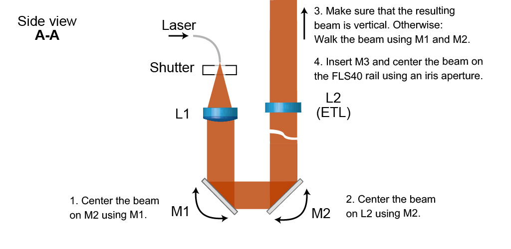
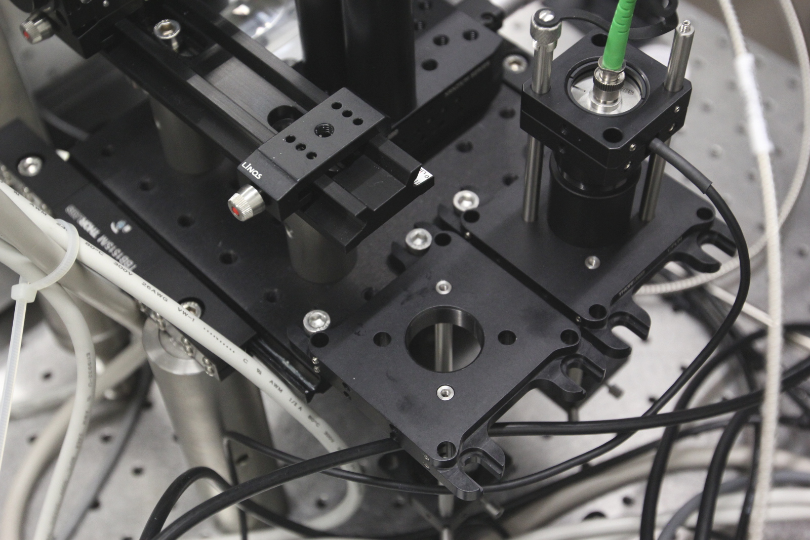
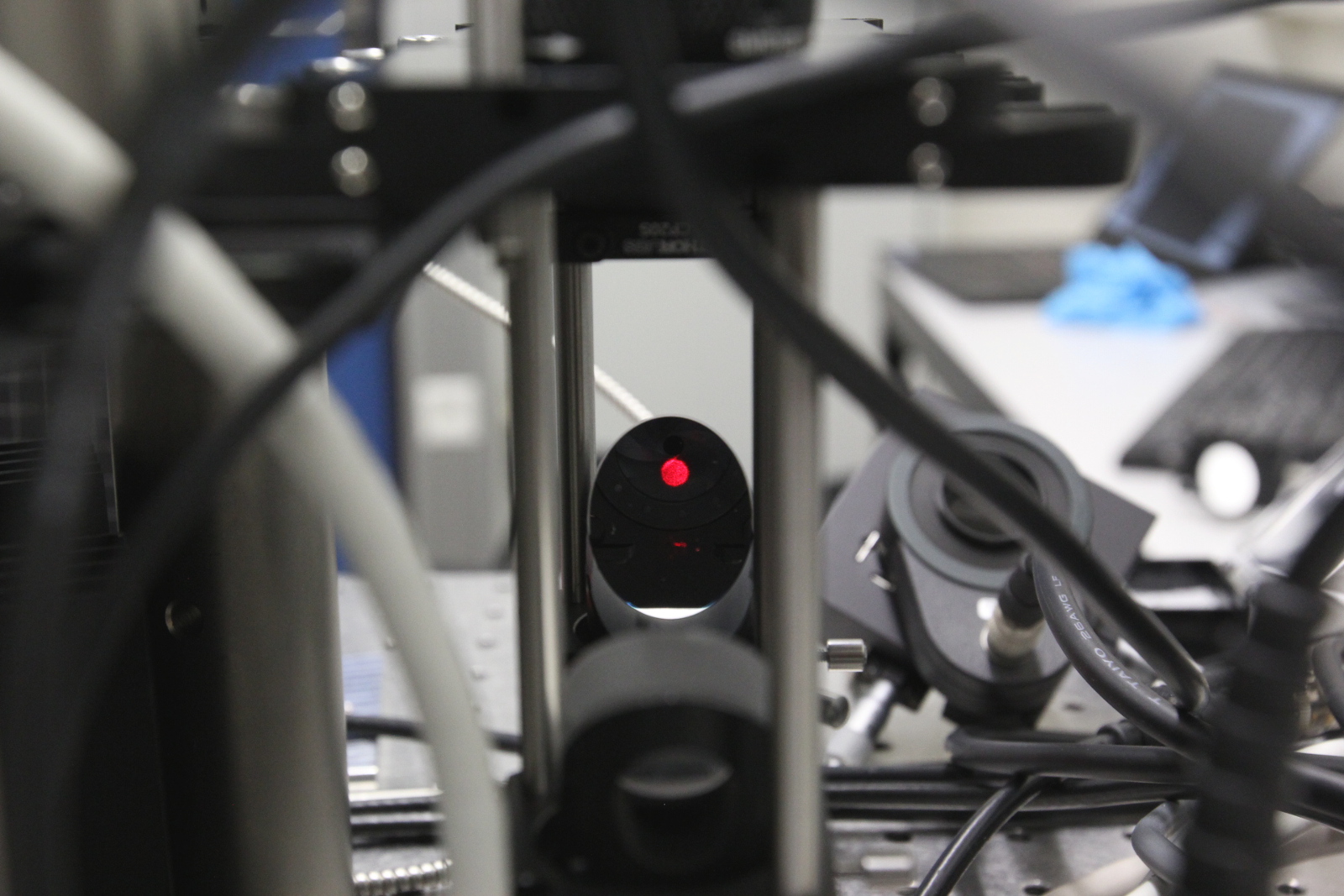
M1 and M2 can then be added to the bottom cage rods suspended below both CPVM plates. Their height above the optical table does not matter. Adjust the position and rotation of M1 so that the laser beam footprint is centered on M2, then align the beam through the ETL so that it propagates along the axis of the raised FLS-40 rail. An iris with a SM1 cageplate on a FLS40 carrier might help with that.

 Centering the beam on M2
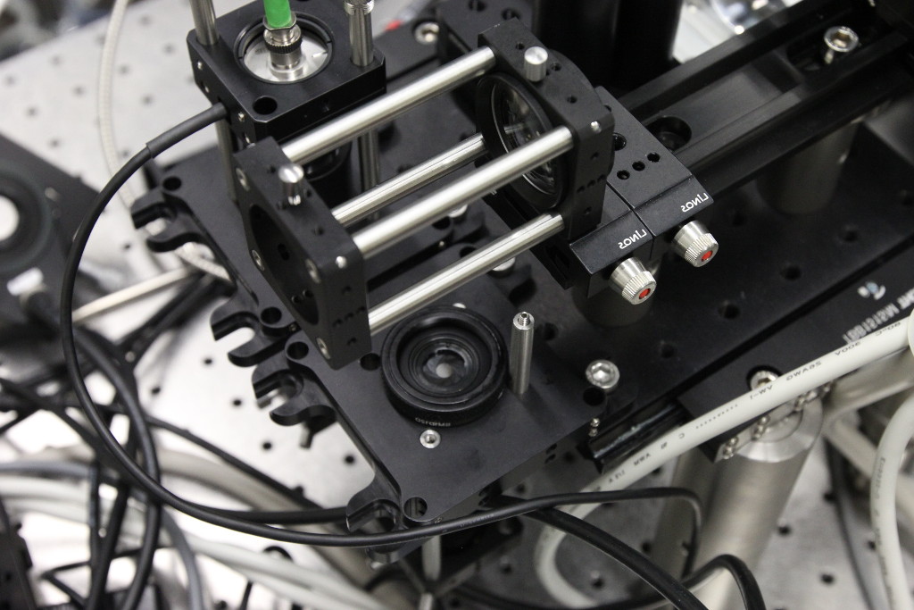
 Prepare the cage rods and cage plate to insert M3. You can use an additional
FLS-40 carrier to mark the position.
-
Background
- mesoSPIM history
- Optical design
- Electronics
-
Setting up a mesoSPIM
- First steps
- Preparing the software and electronics
- Preparing the microscope optics
-
Setting the microscope up
- General alignment tips and tricks
- Installing the microscope base
- Setting up the detection path
- Alignment of the detection path
- Setup of the sample XYZ stages
- Setup of the excitation path
- Immersion cuvettes
- Set up a microscope config file
- Light-sheet co-alignment
- Set up initial ETL parameters
- Setting up lasers with the GUI
- Sample Handling
- Test Samples
- Troubleshooting
- Upgrades and custom variants