-
Notifications
You must be signed in to change notification settings - Fork 4
mesoSPIM_excitation_path
 Overview of the excitation path:
After passing through the shutter aperture, light from the fiber output is
collimated by L1 and then redirected to the electrically tunable lens (ETL). A 1:1 relay than reimages the ETL onto a galvo mirror (M6). By scanning the Gaussian beam in a single axis, a light-sheet is created using a f=50 mm DSLR objective (L5). For simplicity, L5
is drawn as a single paraxial lens instead of showing the internal structure of the
objective. The fold mirrors M1 to M5 render the system more compact. The colors indicate the ray path at different positions of the scan mirror.
 Unfolded design of the excitation path: To illustrate the steps of
the alignment procedure, we are going to use this unfolded drawing
of the excitation path.
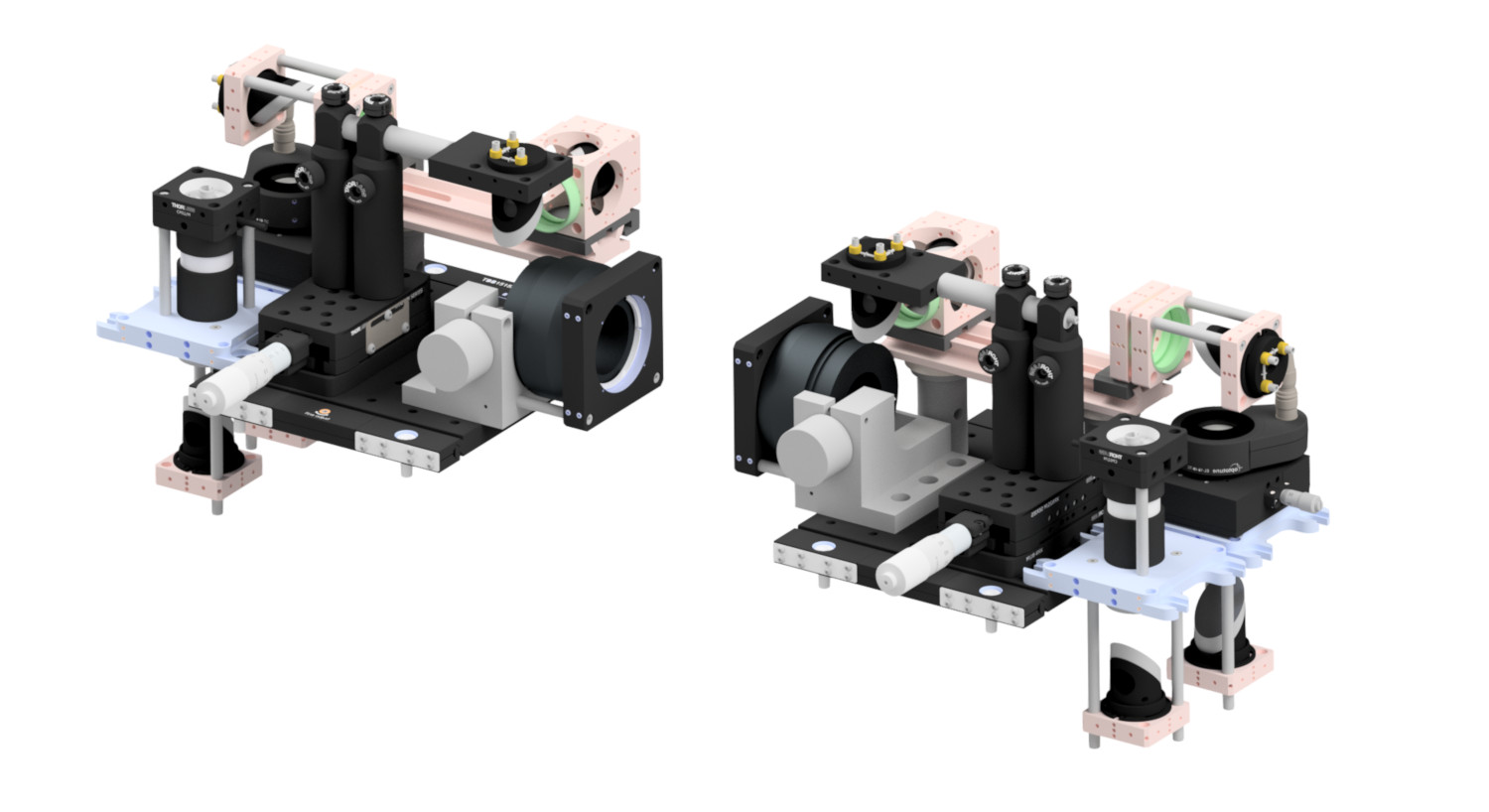
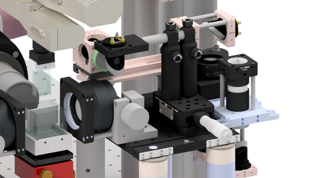
 The excitation path consists of two symmetric units, each placed on a movable 15 x 15 cm breadboard (Thorlabs TBB1515/M). The excitation
paths are identical for mesoSPIM Version 4 and 5, therefore, most images are from Version 4 and some renderings are for Version 5.
Before starting on the excitation path it's a good idea to read the general alignment notes.
It's helpful to place a piece of packing foam on the air table on which to rest delicate parts for short periods


 Please use these renderings as a reference for placing components
After setting up a excitation path, the follwing conditions should be met:
- The excitation light-sheet is orthogonal to the detection axis.
- The distance from M6 (the galvo scanner) to L5 is such that M6 is located in the back focal plane (BFP) of L5. This means that the scanned beam should be telecentric.
- The distances of L2 (ETL), L3, L4 and M6 are set such that L3 and L4 reimage the ETL onto the galvo scanner M6. This means that M6 is in the back focal plane of L4 and the ETL is in the back focal plane of L3.
- The distance between L1 and the fiber output is set so that the beam is collimated for at least one wavelength.
In order to achieve this, a series of alignment steps in the forward direction (fiber output to scan lens L5) and in the backward direction (L5 to fiber output) along the optical path have to be carried out. We will refer to these as forward alignment and backward alignment.
As a light-source for backward alignment, we will use an additional fiber collimator as described here. The collimator can be attached to either the multi-wavelength combiner or an extra laser, for example a helium-neon laser.
You should do all alignment steps with a wavelength in the middle of the wavelength range of your multi-wavelength laser combiner. For example, in a system with 405, 488, 515, 561, 594, and 640 nm excitation lines, 515 or 561 are good options.
⚠️ Make sure that the selected laser line produces a stable high-contrast fringe pattern on the shear plate. If the fringe pattern drifts and jumps without any mechanical movement, the laser is mode-hopping and might need more time to warm up. If this does not stop after a warm-up period, another laser line might be better suited.⚠️ Some laser lines do not produce high contrast fringe patterns For example, high-power (>100 mW) 488 nm lasers tend to be multi-mode instead of single-mode which leads to washed-out fringes. Select a different laser line instead. DPSS lines, on the other hand, usually produce very nice fringes.⚠️ The mesoSPIM excitation path has chromatic aberrations. While the used components (Achromats, scan lens) are all chromatically corrected in the visible part of the spectrum, the mesoSPIM excitation path as a whole has axial chromatic aberration (in the language of optical design, the path is not apochromatic as in a modern confocal microscope). This is not critical, as the electrically tunable lenses (ETLs) can be used to correct for this by applying an offset voltage. Just select a laser wavelength in the middle of your planned excitation lines.
-
Background
- mesoSPIM history
- Optical design
- Electronics
-
Setting up a mesoSPIM
- First steps
- Preparing the software and electronics
- Preparing the microscope optics
-
Setting the microscope up
- General alignment tips and tricks
- Installing the microscope base
- Setting up the detection path
- Alignment of the detection path
- Setup of the sample XYZ stages
- Setup of the excitation path
- Immersion cuvettes
- Set up a microscope config file
- Light-sheet co-alignment
- Set up initial ETL parameters
- Setting up lasers with the GUI
- Sample Handling
- Test Samples
- Troubleshooting
- Upgrades and custom variants