-
Notifications
You must be signed in to change notification settings - Fork 4
mesoSPIM_coalignment
The optical path of the mesoSPIM is set up in a way to streamline co-alignment of both light-sheets. This is done by having an additional linear stage controlling the light-sheet tilt. The "weird" folding of the beam path of the mesoSPIM excitation path is caused by the need to put this linear stage in.
 By putting the last mirror on a linear stage and translating it along the
direction of the input beam, we can adjust the tilt of the light-sheet.
In the ideal case, the tilt is clean (i.e. the pivot point of the light-sheet inside
the sample does not move depending on the pivot angle.) In reality, the pivot
point moves - one reason being that the high-index medium inside the sample
chamber induces refraction of the excitation light-sheet which shifts the pivot point.
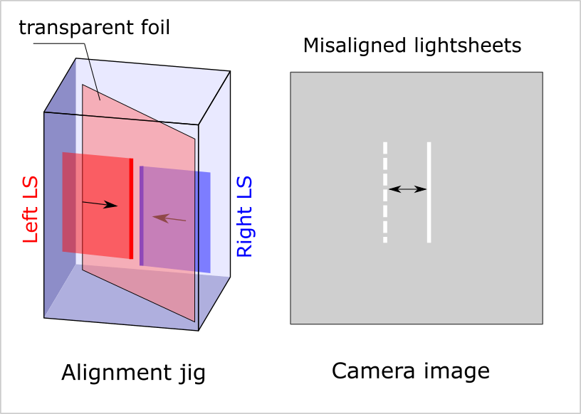
We recommend a simple alignment jig made of thin transparent plastic foil immersed in a RIMs solution (eg Cargille oil) inside a small cuvette. The lightsheet hitting the foil produces some scattered light, which can be easily seen as a bright vertical line on the image (with empty filterwheel position).

Mismatch between left and right lightsheet is clearly visible by the offset between the two lines on the camera image. Moving the alignment jig left-right allows you to probe alignment across the entire FOV.
- use a test sample that is very transparent and homogenous (not your biological sample)
- general alignment: use the alignment jig above. This allows relatively quick alignment, accurate up to about 20 micrometers across the FOV.
- ultra-fine alignment: beads in agarose. Using beads can be tricky if lightsheets are misaligned by more than a few microns.
- pick one side as master and align the other side relative to it
- in the mesoSPIM-control software, go to the alignment tab and click "Run lightsheet switching mode"
- the microscope will now switch the shutter between images
- using the alignment screw on M5 that is closest to L4, adjust both the tilt and offset of the lightsheet till both light-sheets overlap in the center of the image
- using the linear stage, adjust the tilt of the light-sheet till both light-sheets overlap at the edges of the image
- move the alignment jig left/right across the FOV to probe center and edges of the field.
- usually, several iterations of the last 3 steps are necessary
- If you are very far out of alignment:
- remove the immersion cuvette
- put rods through the 60 mm cage plates from one excitation path to the other
- if you noticed the cage plate with the objective is sagging downwards then likely that means you need to use slightly longer ER rods to support it
- use 60 mm alignment targets to check the beam, move the target back and forth along the light-sheet propagation direction for alignment
- use M5 tip/tilt and linear translation to align the beam along the axis of the 60 mm cage system
 Using a 60 mm alignment target to check the light-sheet propagation
- even the smallest index variations and slight cuvette rotation (<1 degree) can lead to misalignment of two very thin light-sheets
- when changing immersion media or clearing methods, realignment of both light-sheets relative to each other is likely to be necessary
-
Background
- mesoSPIM history
- Optical design
- Electronics
-
Setting up a mesoSPIM
- First steps
- Preparing the software and electronics
- Preparing the microscope optics
-
Setting the microscope up
- General alignment tips and tricks
- Installing the microscope base
- Setting up the detection path
- Alignment of the detection path
- Setup of the sample XYZ stages
- Setup of the excitation path
- Immersion cuvettes
- Set up a microscope config file
- Light-sheet co-alignment
- Set up initial ETL parameters
- Setting up lasers with the GUI
- Sample Handling
- Test Samples
- Troubleshooting
- Upgrades and custom variants