-
Notifications
You must be signed in to change notification settings - Fork 86
PureSignal
This under construction page captures how to setup and use Pure Signal with a Hermes-Lite 2.
A very complete document from Christoph DL1YCF is available here and should be read in conjunction with the information in this wiki. Basically pure signal also known as adaptive predistortion is a method of sampling a transmitted signal and applying a polynomial to produce a driving signal which is distorted by the algorithm so that it corrects the non linearities in the output. It needs to have a memory of the signal so that it is not constantly trying to correct its corrections and the result can be 10 dB or more improvement on higher order products which means less splatter, better speech quality and higher efficiency. Almost impossible to do in analogue radios but perfect for SDR like the Hermes-Lite 2.
Assuming a fairly standard 100 Watt Linear amplifier, it is necessary to feed some of the output signal back into the Hermes-Lite so it can sample it to calculate the adjustment to the transmitted signal for the pure signal correction. The Hermes-Lite2 should have the psfeedback unit described here by Steve KF7O and in my case I made an L network with R1 = 0 ohm, R2 = 56 ohm and R3 = 470 ohm while R4 was omitted. The total attenuation for this is approximately 25 dB. With 100 Watts out (+50 dBm) tapped through the directional coupler's 36 dB loss = +14 dBm and a further 25 dB from the HL2 psfeedback = -11 dBm (63 mV) of feedback signal applied to the HL2 receiver which is nicely in the middle of the range required.
A simple way of getting a sample of the output signal which is reasonably constant over the frequency range is to build a power tap utilizing one section of a Stockton Bridge. It is easily constructed in an evening and cheap. It is simply a toroid with 30 or so turns threaded over a piece of coax. A very full treatment of directional couplers is given by Jeff Anderson K6JCA and there is a lot more information on his site in his directional coupler series.
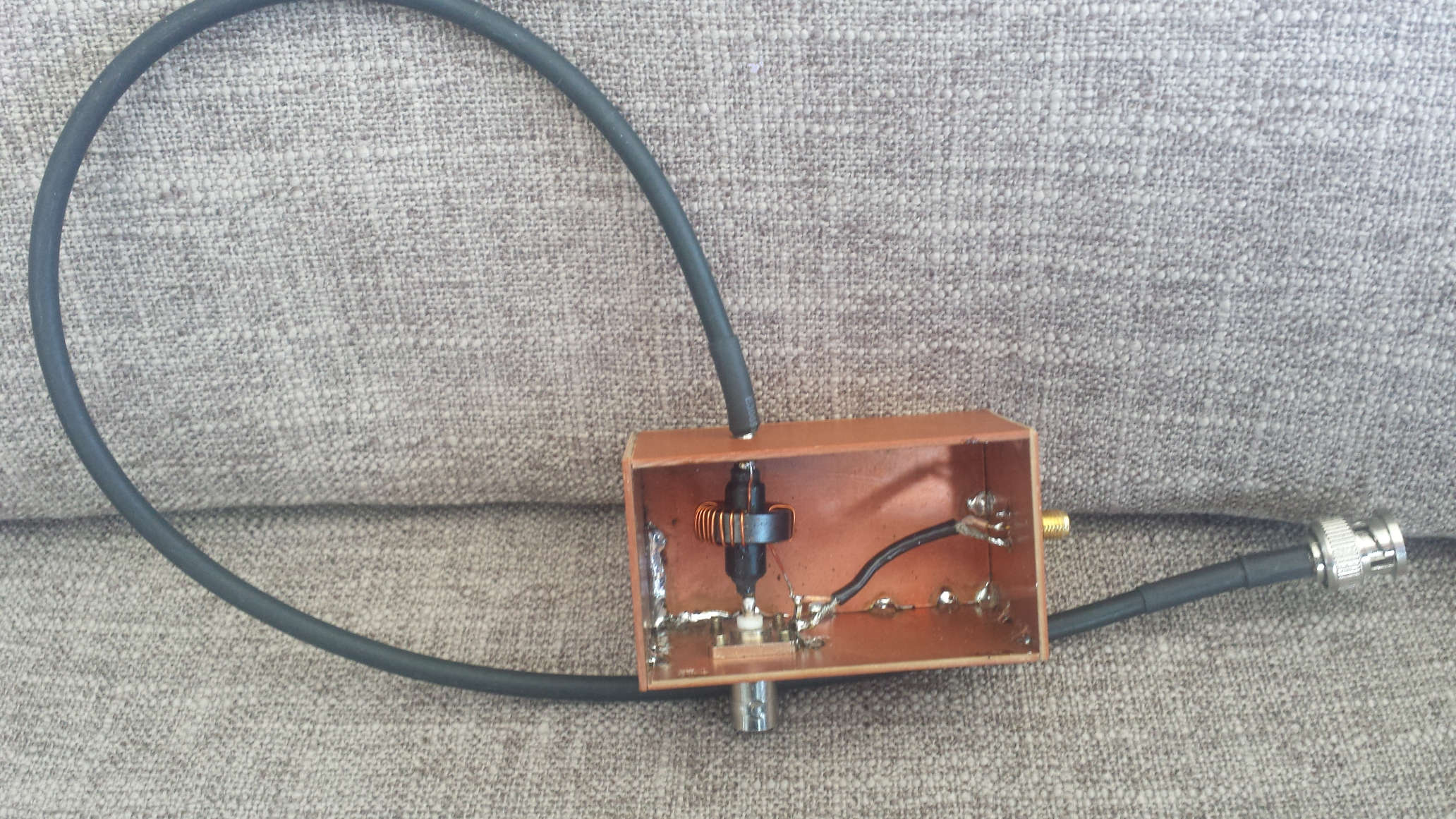
Most HF ferites are suitable for the toroid and as it handles little power anything that will fit over the coax and hold the turns will do. I used an 18 mm L8 toroid from Jaycar but an FT50-43 would have done just as well. I wound on 30 turns and made a box from phenolic (FR2) PCB. I stripped the covering off the braid and soldered it directly onto the box and terminated the other side in a BNC socket as shown below.

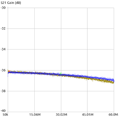
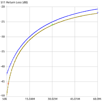
The tap is terminated in a 50 ohm resistor earthed at the BNC socket and a short length of RG174 runs to an sma connector on the end of the box. VNA sweeps of the tap performance are shown below


The bronze trace is with the RF applied from port 1 to the cable side of the coupler and the BNC connector terminated on 50 ohms while the blue trace is with the connections reversed. In both cases port 2 of the VNA connects to the sma connector.
The values obtained from the coupler are:
| 1 MHz | 30 MHz | 60 MHz | |
|---|---|---|---|
| S21 gain | -36.182 | -36.516 | -36.923 |
| S11 Ret Loss | 46.078 | 25.381 | 20.981 |
Interestingly the tap does introduce some return loss although it is not significant and the S21 coupling loss of around 36 dB varies only 0.33 dB over the range of 3 to 30 MHz.
Under Construction
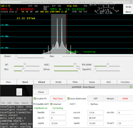
In piHPSDR simply choose Menu/PS and you will be presented with the following screen

On the upper left, check the "Enable PS" and "Auto Attenuate" check boxes and turn "MON" button on (Button text goes red).
On "PS Feedback ANT" there is a choice of Internal, EXT1 or ByPass (EXT1 and ByPass appear to be the same currently). These are chosen on the basis of the amount of feedback from the transmitter and will vary with the level from the power tap used. In the example used here the level presented to the Rx for pure signal monitoring is about +8 dBm from a 100 watt signal so the High attenuation input is selected by choosing EXT1. If you are running the HL2 barefoot you probably will need the Internal checkbox to get enough signal.
Try to get the TX ATT reading to be in the range of 10 to 20 but it will work beyond these values. At TX ATT value 31 you will be Rx clipping and PS will be distorted. If your TX ATT reading is over 25 I suggest that you add some more attenuation to your Power Tap feedback path.
PS is turned off by clicking the "OFF" button and you will note that the "feedback", "cor.cnt" etc. status boxes freeze. It is turned back on again by clicking the "Restart" button.
In MON mode, you are observing the actual output of your transmitter which Christoph DL1YCF has checked against a spectrum analyser and finds good agreement. With MON off you are observing the correcting signal and if you turn off PS it will disappear.
Again I urge you to read the document referenced at the beginning of this wiki and also visit his web page where he has tabulated a lot of experimental data beyond the scope of this wiki. Christoph wrote the PS routines and developed the piHPSDR algorithms so his information is 100% relevant.
Under Construction


A barefoot HL2 with pure signal feedback applied from a 36 dB power tap. On the left pure signal is disconnected but there is sufficient feedthrough from the changeover relay leakage and strays to get sufficient signal to activate the pure signal. On the right hand picture the signal has improved very little but note that the TX ATT is has been set automatically from 17 to 22 due to the extra input signal from the power tap.


Here the signal is compared with and without PS applied. Due to the extra 95 watts above the 5 Watt barefoot HL2 (100 W out) it was necessary to use the EXT1 levels to avoid Rx clipping and the TX ATT has adjusted to 16 to keep the signal in the required range for the HL2 monitoring receiver. The unwanted products have dropped from -30 dBc to -45 dBc with the application of pure signal, an improvement of 15 dB. Not bad for $10 worth of parts and an evening's fun.