-
Notifications
You must be signed in to change notification settings - Fork 0
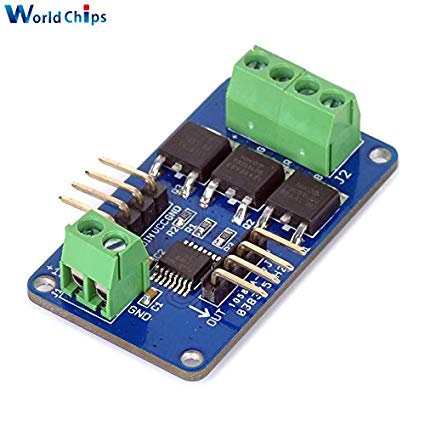
RGB LED Strip Driver

These LED driver are designed to drive a 5m strip of LED lights at up to 12V with the color controlled from an Arduino. These drivers can be daisy chained together sharing the control signal and operating on lockstep.
The 2 wide screw terminal is for the power supply. The 4 wide terminal is for the output to the LED strip V+, Green, Red, and Blue. The 4 wide input is for Clock in (CIN), Data in (DIN), +5V (VCC), and GND.
The board is using a P9813 chip set to manage the serial data from the Arduino and drive transistors to modulate the amount of current to each color channel.
The easiest way to get up and running is to use the FastLED library.
- Wire everything up.
- Set your CIN and DIN pins.
- Set the number of LEDs to 1. (This chipset doesn't support addressable LED strips, the whole strip acts as a 'single LED address')
- Initialize the library to the P9813 chipset.
- Do lighting calls.
#include <FastLED.h>

#define NUM_LEDS 1
CRGB leds[NUM_LEDS];

static const char DATA_PIN = 12;
static const char CLOCK_PIN = 13;

void setup() {
    FastLED.addLeds<P9813, DATA_PIN, CLOCK_PIN, RGB>(leds, NUM_LEDS);
}

void loop() {
  // Turn the LED on, then pause
  leds[0] = CRGB::Red;
  FastLED.show();
  delay(500);
  // Now turn the LED off, then pause
  leds[0] = CRGB::Black;
  FastLED.show();
  delay(500);
}
If you use pins backed with hardware SPI the FastLED library will use hardware rather than bit bashing for the communication.
On the Arduino Uno or Duemilanove that is pin 11 for data and pin 13 for the clock.
SPI docs