-
Notifications
You must be signed in to change notification settings - Fork 0
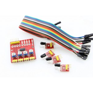
4 Channel IR Sensor
A cheap package with 4 IR sensor units and breakout board to collect the signals. The sensors can be used for short range distance measuring or for light/dark color detection. The sensitivity can be tuned per sensor using trimpots on the breakout board.
I plan on using this to build an absolute position encoder.

Turns out this device outputs an analog signal in proportion to the amount of light the sensor collects.
This is really good if you need to get distance values out, but for an encode it's not ideal.
See updates at the bottom of the page
I planned to use the interrupt pin on the Arduino to detect when we crossed an encoder boundary, but we really need the signal to be digital for that to work. A simple comparator circuit for each channel will let us set a voltage threshold (with a trimpot) above which will output a HIGH signal and below will output a LOW. Then we get to use interrupts again. I'm thinking about using something like an LM339 ic as it has 4 comparators in the one package running off a common voltage.
The LM339 is build in already! See updates at the bottom of the page
The other option would be to just poll the sensors at a fixed rate, but that sounds less efficient to me.
The breakout board had six male header pins to connect to host the Arduino.
- VCC
- GND
- Signal A
- Signal B
- Signal C
- Signal D It also has four sets of headers (3 Pins each) that connect to the sensors.
Each sensor unit is an IR emitter and IR receiver on a board with three male header pins.
- VCC
- GND
- Signal
Specifications
- Operating voltage: DC 3.3V-5V
- Operating Current:>1A
- Operating temperature: -10 ℃ - +50 ℃
- Mounting Hole: M3 screws
- Detection distance: 1mm to 60cm adjustable
- Size: central control board:42mm x 38mm x 12mm
- Small board: 25mm x 12mm x 12mm
- Output Interface: 6-wire (1234: signal output, +: positive supply -: ground)
Documentation http://www.energiazero.org/arduino_sensori/4_channel_line_tracker_sensor.pdf
On closer inspection, the board is already running an LM339. I think I will need to take some measurements and understand the board a bit better before I commit to an approach.
The board is using the LM339 outputs to sink the signal. It also looks to be running without the VCC line connected to the IC?!? I need to check with a voltmeter, maybe the connection is just under the chip...
The configuration of the phototransistor. A phototransistor like a normal transistor has a collector and an emitter, but the base signal is provided by the energy of the photos hitting the doped semiconductor.
In this configuration, the signal will go low when photos are detected.
I built up a sample copy of the circuit in LTSpice to try and figure out how it works.
 It looks like the actual output should be quite sharp. I still don't understand when I see dimming in the D4 indicator LED on the physical device.
Success! After breaking out the multimeter and graphing a bunch of values I have concluded that the output is indeed digital. The comparator is working as expected and matches the simulation. The LED dimming I was seeing was the output signal bouncing rapidly between LOW and HIGH causing pulse width modulation (PWM).
