This repository describes how to interface with the Modbus connection on Chofu heat pumps, also marketed as the Grant Aerona3.
Thanks to guesswork and reverse engineering, tables of Modbus parameters are provided. We have successfully interfaced them to Home Assistant.
-
A 3-core cable to connect to your outdoor heat pump unit, ideally screened. Our example installation had an existing shielded F/UTP cat5e cable for connecting the relay inputs, with two unused pairs, so those were used.
-
A Modbus interface. This can be either serial (RS485)-based or network-based. Modbus offers standard protocols for Modbus-RTU (serial) and Modbus-TCP (network) so in theory any interface supporting these should work.
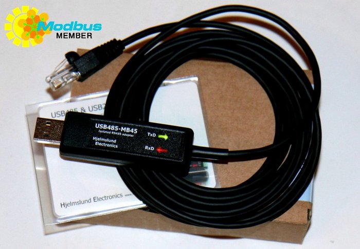
This has been confirmed working with a Hjelmslund USB485-MB45 isolated USB-RS485 converter:
and a USR-W610 Wi-Fi/Ethernet to Modbus adapter:
but these are the interfaces we had available, rather than specific recommendations. USB RS485 interfaces are available for a few pounds/euro/dollars on eBay and will probably work - we would recommend isolated interfaces, especially if you have multiple phases available and your heat pump may be on a different phase to your computer.
-
A suitable termination for you're adapter's RS485 interface. If it terminates in an RJ45 plug, that could be a network wall box and RJ45 front plate. If your adapter terminates in screw terminals, you may not need additional hardware.
-
A computer on which to run Home Assistant, or an existing HA setup. Follow the Home Assistant Getting Started and other guides, which describe the hardware you need. We used a Raspberry Pi 3. From here on we'll assume you have Home Assistant installed and basic configuration done.
-
Remove the side panel of your outdoor heat pump unit to reveal the interface PCB:
Note the three pins at the bottom of the main connection block:
- 15: RS485 + (lower level)
- 16: RS485 - (lower level)
- 32: RS485 GND (upper level)
You need to attach wires to these three terminals. GND should go to your cable screen.
In this case:
- RS485 + = orange
- RS485 - = orange/white
- GND = green+green/white (the F/UTP shield had been clipped back so was unavailable)
-
Run these wires to where you want to mount your USB-RS485 or network-modbus adapter. Here they were in our indoor utility cupboard, a cable run of about 7m.
-
If using an RJ45 adapter, there is a standard pinout. From the Modbus serial line specification:
these are connected as follows:
ASHP RJ45 pin Modbus signal RS485+ (orange) 5 D0 RS485- (org/wh) 4 D1 GND 8 GND -
Service mode on the heat pump (see the service manual ) has a series of parameters for configuring Modbus:
It is probably fine to leave these as-is, just to remember the connection has Modbus enabled by default, uses address 1, with 19200 bps, no parity and two stop bits. If using a Modbus-TCP device you will likely need to configure it appropriately.
- Once connected, a simple way to test is via the mbpoll tool. With it we can read some temperatures out of the heat pump using a Modbus-RTU serial device on /dev/ttyUSB0:
$ mbpoll /dev/ttyUSB0 -b 19200 -d8 -s2 -Pnone -0 -r0 -c10 -t3
mbpoll 1.4-25 - FieldTalk(tm) Modbus(R) Master Simulator
Copyright © 2015-2019 Pascal JEAN, https://github.com/epsilonrt/mbpoll
This program comes with ABSOLUTELY NO WARRANTY.
This is free software, and you are welcome to redistribute it
under certain conditions; type 'mbpoll -w' for details.

Protocol configuration: Modbus RTU
Slave configuration...: address = [1]
                        start reference = 0, count = 10
Communication.........: /dev/ttyUSB0,      19200-8N2
                        t/o 1.00 s, poll rate 1000 ms
Data type.............: 16-bit register, input register table

-- Polling slave 1... Ctrl-C to stop)
[0]: 	38
[1]: 	0
[2]: 	56
[3]: 	0
[4]: 	0
[5]: 	8
[6]: 	7
[7]: 	0
[8]: 	14
[9]: 	39
For a network device, the syntax is:
$ mbpoll <hostname> -0 -r0 -c10 -t3
If this doesn't work, check your wiring and settings.
Home Assistant has its own Modbus implementation, so we simply need to add
to the HA configuration.yaml file (there is no configuration GUI).
-
If you don't know how to edit your configuration.yaml, we suggest installing the File Editor addon via Supervisor, enabling the 'Show in sidebar' toggle. You can then find the File Editor in your HA sidebar, select it, and choose configuration.yaml.
-
Copy and paste our configuration.yaml fragment and add it to the end of your file. Edit the connection settings at the top of your
modbus:section. Save the file.If using an ethernet gateway, you can use the following configuration.yaml fragment
-
In Configuration -> Settings click 'Check configuration', to ensure there are no syntax errors. If all is good you can 'Restart' your Home Assistant.
-
Various
ASHP ...readings should now show in 'Entities', and in the Sensors box on the front page, if using the default panel. -
If you click on a reading, a graph of the reading will be shown. You can also access graphs via the History page, like any other Home Assistant data.

grantstephens contributed a config for ESPHome for monitoring with a serial to RS485 converter.


