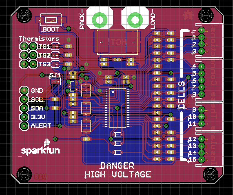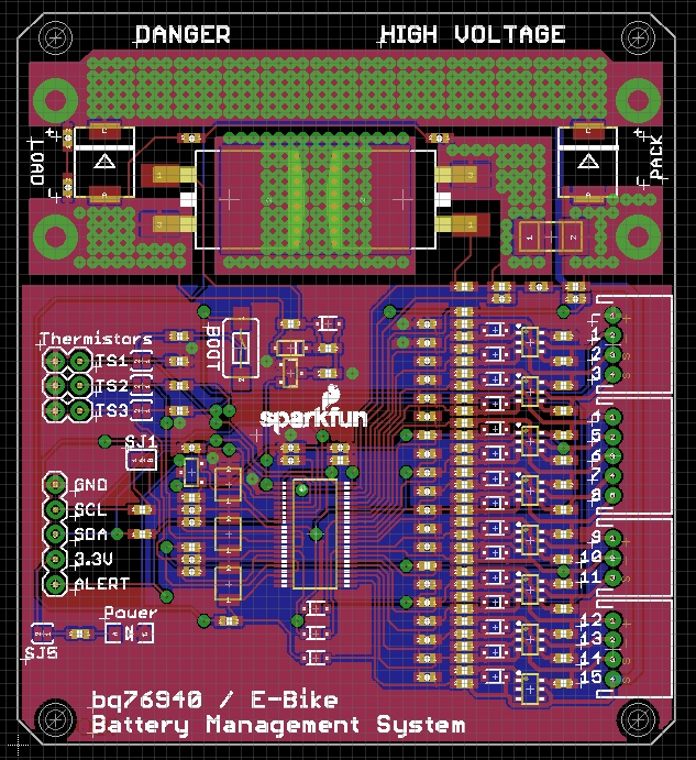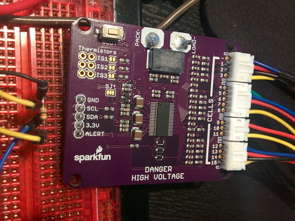
This is a breakout board for the BQ76940. This configuration allows for 15 cells to be read. There is no safety cut off.
This is a dangerous board that exposes the user to over 48VDC and many amps. Please use responsibly.
v1 of the board is functional. Firmware is working. Most functions are written.

-> v2 of the board has full cutoff MOSFETs and charging MOSFETs. <-

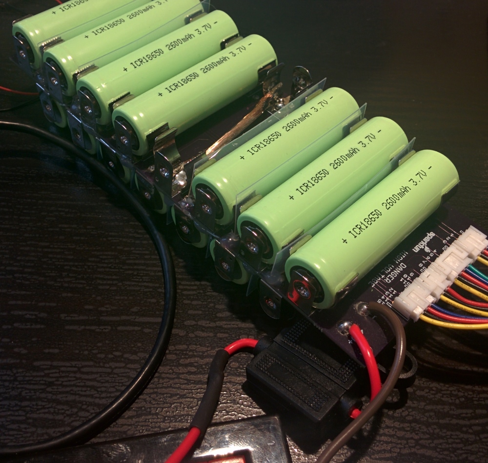
v1 of the test pack works but has multiple errors that are fixed on v2. Number labels on the cells are reversed. Cells 9 and 14 were shorted to bring the voltage back down to 48V. The clips are very close together so plastic insulators were glued in place.
This code is public domain but you buy me a beer if you use this and we meet someday (Beerware license).
