-
Notifications
You must be signed in to change notification settings - Fork 2
Hardware Implementations
Using the Arduino core interface allows the firmware to be compiled for different hardware implementations with limited adjustments. For the test implementations, for example, there are only modifications to the specific hardware GPIOs being used for the most part.
Details of the known implementations are provided here.
The primary design for deployment of a low-cost logger uses an ESP-WROOM-32 System-on-Module (SoM) which includes an ESP32 dual-core processor, 4MB flash storage, and a PCB antenna for WiFi. This module also provides a direct high-speed SD interface, a CAN bus controller (apparently equivalent to an SJA1000 chip), and UARTs for RS-422, so that there are minimal external requirements: a CAN bus transceiver, an RS-422 transceiver and opto-couplers along with a DC-DC converter for isolated receive of NMEA0183, and a micro-SD card holder and card (along with a power regulator, passives, and physical connectors).
The simplest version of this can be done with a simple breakout module and external discrete components:
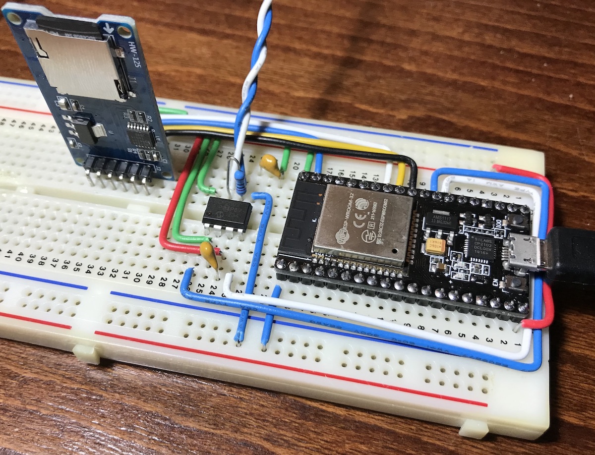
although the more sophisticated WIBL (Wireless Inexpensive Bathymetry Logger) integrated version of the design:
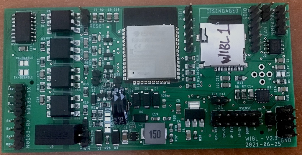
is generally preferred, and is described in detail here. Manufacturing information for the latest version of WIBL, including schematic, board layout, bill of materials, and pick-n-place positions, suitable for production through JLCPCB are provided on the project's website.
The implementation uses the standard CAN bus interface on GPIO16 (TX) and GPIO17 (RX). Any plausible CAN transceiver can be used; the reference design uses the TJA1051T/3.
The implementation uses UART1 and UART2 for the two receive channels, which are mapped to GPIO34 (RX1) and GPIO35 (RX2). The TX side is generally not used, but can be useful for making a hardware data simulator, and the two channels are mapped to GPIO18 (TX1) and GPIO19 (TX2).
The system design includes a small six degree of freedom IMU (three axes of acceleration, three axes of gyro rate measurements), the LSM6DS3. This is relatively cheap and easy to interface through the I2C bus on GPIO22 (SCL) and GPIO21 (SDAT), and can provide relatively rapid motion estimates if required (certainly fast enough to monitor the motion of smallcraft). The reference design has 10 kΩ pull-up resistors for I2C; these may need to be adjusted for other implementations. The IMU interrupt line is connected to GPI37 (module pin 5) to allow the logger to react to new data being available, rather than polling the device. By default, the firmware configures the IMU for 13Hz updates, 245 degrees/s full scale on the gyros, and 4.0G full scale on the accelerometers.
The standard SD/MMC interface on the ESP32 module is used; 47 kΩ pull-up resistors are used for all lines (opinions differ on whether this is wise, but it does appear to work). This interface requires:
- DATA0: GPIO2
- DATA1: GPIO4
- DATA2: GPIO12
- DATA3: GPIO13
- CLK: GPIO14
- CMD: GPIO15
Note that these lines cannot be reassigned, since they are tied directly to the SD/MMC protocol controller on the ESP32 (the second of two, the other being used for the on-module flash). The module also uses GPIO2 and GPIO12 for boot-strapping pins (i.e., to configure the module during the boot process), and therefore the system pulls those low when attempting to go into programming (download) mode, along with GPIO0 (which sets the module into download) so that the system boots appropriately.
By default, the firmware assumes that the red, green, and blue LEDs will be present on GPIOs 25, 26, and 27. They do not need to exist, however, for the hardware to work: these are mostly just useful for debugging during development.
For development, the better-developed Arduino Due platform was used, along with an Adafruit Datalogger Shield to provide the SD card interface, and the Adafruit Bluefruit SPI friend for Bluetooth LE connectivity. The Due has a native CAN bus controller, and uses the MCP2562 chip for a CAN transceiver.
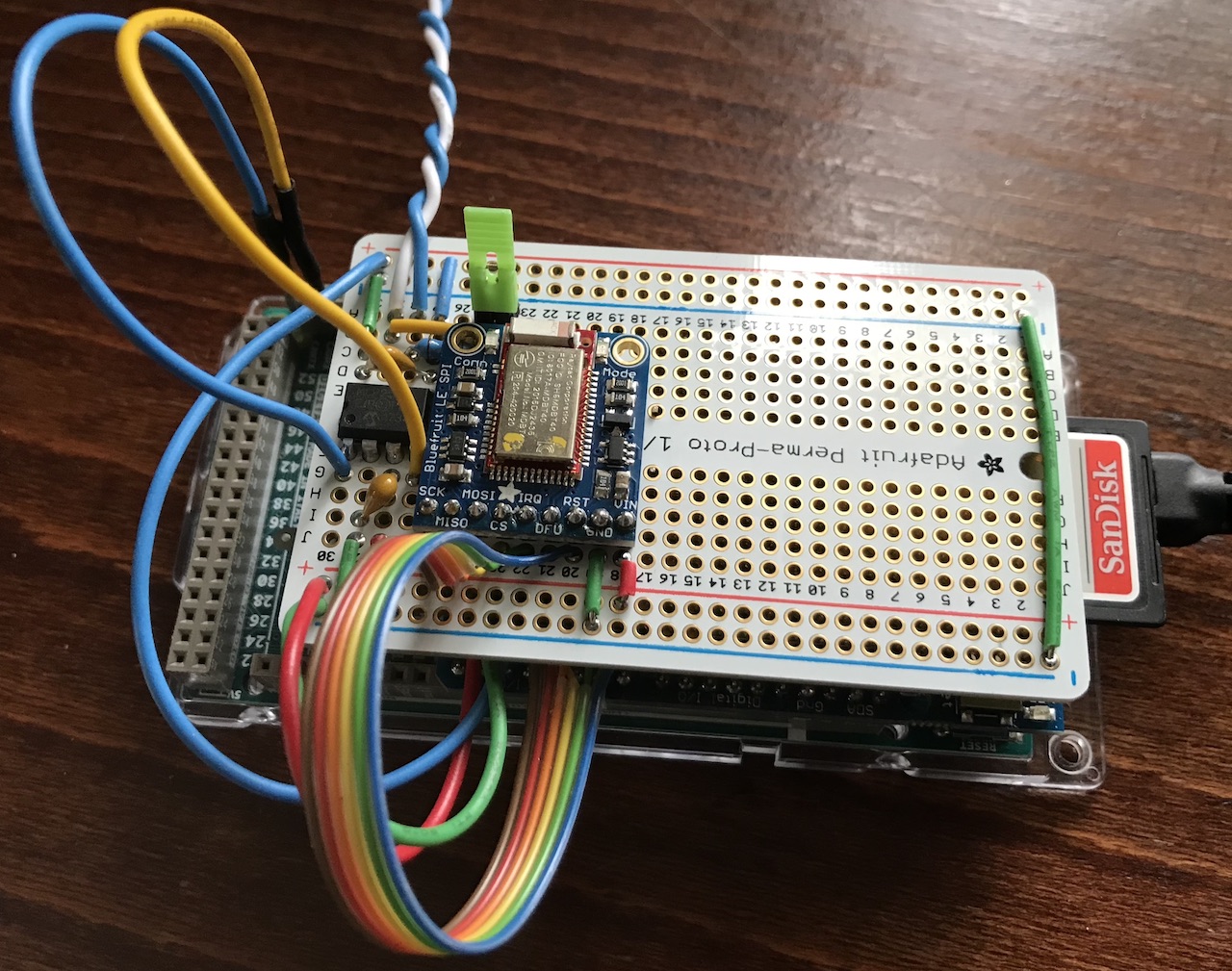
Note that BlueTooth is not used in hardware versions 2.0 and above.
The Arduino Due has hardware SPI interfaces, but the Adafruit Datalogger Shield sits on the ICSP connector, and does not pass-through the SPI lines. Consequently, the hardware SPI implementation can't be used for connection to the Bluetooth module. Software SPI is used instead. This uses pins:
- SCK: GPIO2
- MISO: GPIO3
- MOSI: GPIO4
- CS: GPIO5
- IRQ: GPIO6
- RST: GPIO7
By default, the firmware assumes that the red, green, and blue LEDs will be present on GPIOs 8, 9, and 22. GPIOs 8 and 9 are the on-board LEDs on the Datalogger shield (green and red, respectively). GPIO 22 for blue is essentially chosen at random, and isn't really required for V1.0 of the logger hardware.
The implementation uses UART1 and UART2 for the two receive channels, connected to GPIO19 and GPIO17, respectively. The TX side is not used.
The Datalogger shield automatically taps into the hardware SPI interface present on the ICSP connector on the Due, but uses GPIO 10 for chip-select on the SD card. This is the default for the card, and therefore requires no modification.
In order to test logging NMEA data, a simple transmitter of NMEA2000 and NMEA0183 data can be constructed by re-flashing a WIBL logger with new firmware.
A number of different approaches to manufacturing have been tested. Initially, a "plug in module" version of the board was facilitated by building a PCB through OSH Park, who aggregate small-run PCBs into panels and then have the panel fabricated through a partner fab. The resulting board:
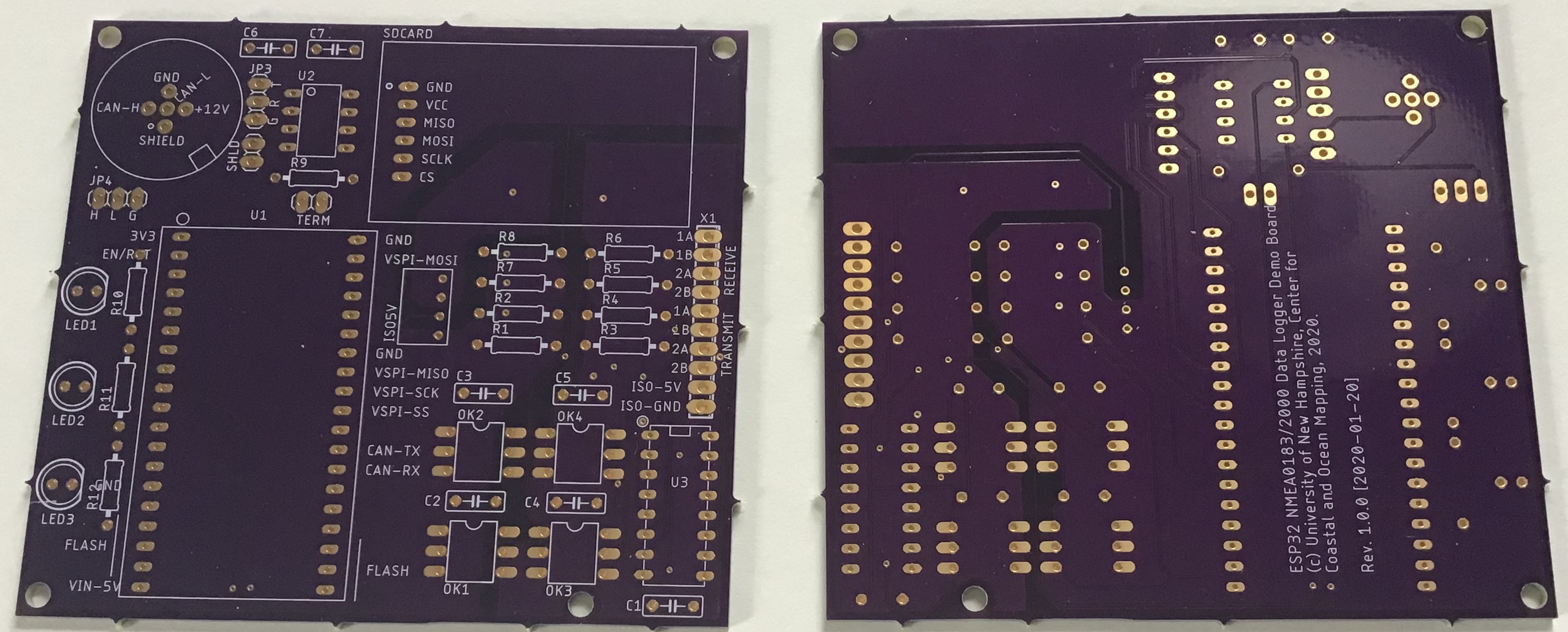
is designed to be used with through-hole components and sub-modules (e.g., the SD card), making assembly a lot simpler (although a little less dense). This system, built from a version of this schematic, contains slightly more hardware than would be required for a standard data logger, and provides for fully-isolated transmit and receive channels for the RS-422 data, allowing the system to be used as a data generator in addition to a data logger. RS-422 interface is by miniature screw terminals (right hand side), while NMEA2000 interface is via the standard male plug (top left), with optional termination and cable-shield to ground via pin headers.
The board is populated in height order:
with:
-
Resistors.
-
19-pin headers for ESP32 module.
-
DIL sockets.
-
Capacitors.
-
Pin headers for jumpers, etc.
-
LEDs.
-
Screw terminal block.
-
DC/DC converter IC.
-
NMEA2000 socket.
The SD card module can be added at any point. Fitting the ESP32 module into the 19-pin headers can be problematic, since the pin pitch doesn't appear to be exactly 2.54mm as might be expected.
A CCOM Industrial Partner, SeaID, has committed to building a commercially supported low-cost logger, called NEMO-30:
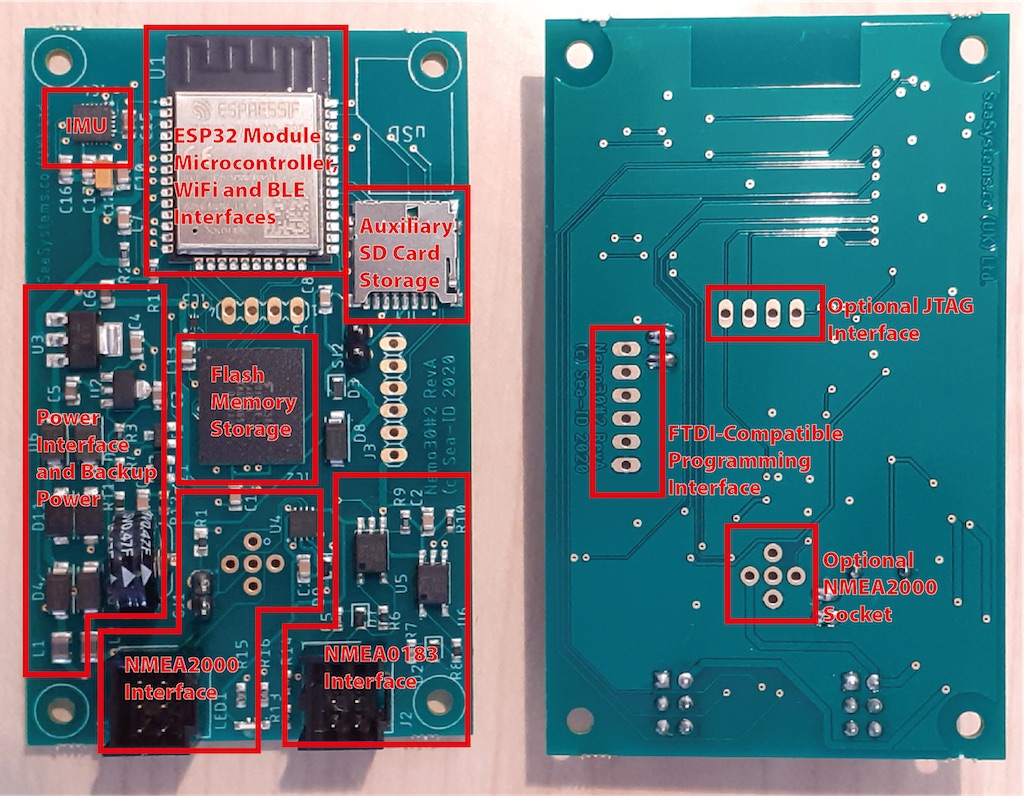
For details, contact SeaID.
Assembling boards by hand can be difficult and time consuming, and a number of fabrication houses now provide Surface Mount Device assembly services in addition to PCB construction. An example of this has been developed to demonstrate the possibility, and to assess the costs of manufacturing. The resulting board:
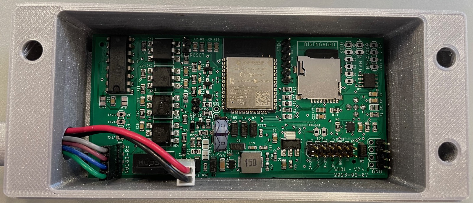
integrates all of the components for the board, as detailled above. Note that the board shown, v 2.4.1, is designed to allow the use of a DIP version of the RS-422 transceiver (top left in image), rather than an SMD version, which can be hard to procure for manufacturing. The v 2.3.1 board has the configuration for SMD. All manufacturing files are available in the project website.
A switch-mode power supply is used to transform down from the nominal 12V input to 5V, and an LDO is then used to generate the 3.3V power supply for the ESP32, SD card, etc. The board is based on this schematic, and this PCB layout. Board manufacturing files (Bill of Materials, Pick and Place) are also provided in the project website, along with Gerbers, formatted for construction at JLCPCB.
There are many possible ways to encapsulate the board so that it can be taken into the field. The initial implementation for NMEA0183 used an IP65 enclosure to provide a measure of protection from the environment:
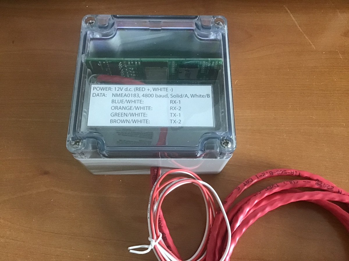
The data wiring for the NMEA0183 is Cat-6 Ethernet unshielded twisted pair, using one pair for each receive and transmit channel. The colour-coding is arbitrary, but the current implementation is:
- Blue/White (Ethernet pair 1): Receive channel 1.
- Orange/White (Ethernet pair 2): Receive channel 2.
- Green/White (Ethernet pair 3): Transmit channel 1.
- Brown/White (Ethernet pair 4): Transmit channel 2.
In each case, the solid coloured wire is used for the "A" line, and the white wire (with matching colour stripe) for the "B" line. So, the blue wire is RX-1A, and the white with blue stripe is RX-1B, etc.
In order to bring the price down a little, the v 2.4.1 boards use 3D-printed enclosures:
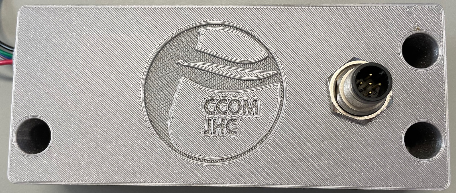
the STLs for which are available in the manufacturing archive. Typical materials costs in PLA are $3.50 (2023-03).
