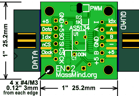
Arduino Library for the Massmind AS5134 rotary encoder. This library communicates with the encoder using 3-wire serial mode. More information about the encoder can be found here.
This encoder has quadrature output as well as incremental angle output and multi-turn counter output. This library provides simple reading of the angle and turn count values from the encoder.
Create:
Create an instance of the class.
AS5134 encoder(dioPin, csPin, clkPin);
dioPin - digital IO pin for trasmitting data. csPin - chip select pin. clkPin - clock pin.
Initialize:
Initialize the class. Should be run in the setup() Arduino function.
encoder.init();
Read Angle:
Get the absolute angle value in degrees.
angle = encoder.readAngle();
angle - Absolute angle value in degrees (0 to 359).
Read Multi-Turn Angle:
Get the total angle value from the starting position.
totAngle = encoder.readMultiTurnAngle();
angle - long int with the total angle value in degrees.
Read Counter:
Read the multi-turn counter.
count = encoder.readCounter();
count - Signed integer holding the multi-turn value.
Reset Counter:
Reset the multi-turn counter to zero.
encoder.resetCounter();
Datasheet: https://www.mouser.com/datasheet/2/588/AS5134_Datasheet_EN_v4-318114.pdf
Wiring:
Make connections to the encoder as follows:
dioPin -> Data/SO
csPin -> nCS/CS
clkPin -> Clock/CK
5v -> 5v
gnd -> gnd
Also, the Data/SO pin must be pulled low for communications to work correctly. To do this, add a 10k resistor between ground and that pin.
Using Multiple Encoders:
To reduce wires and conserve pins when using multiple encoders, a common DIO pin and CLK pin can be used for all devices. Each device will then have a unique CS (chip select) pin which will be used to choose the active device.
