-
-
Notifications
You must be signed in to change notification settings - Fork 532
Motor Ganging and Axis Squaring
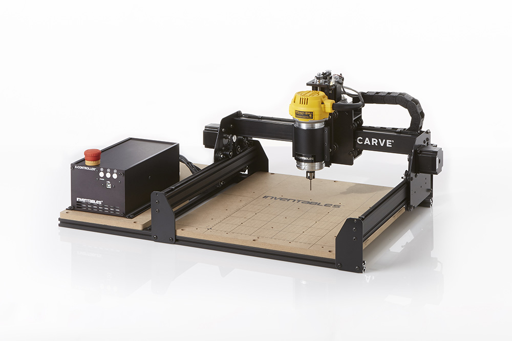
A lot of gantry type machines use (2) motors on one axis, with a motor at each end. This provides extra power and can prevent the racking that would result from driving from one side. You do have the problem of making sure the machine is square to start with.
Grbl_ESP32 can help with this. Any axis can use (2) motors and these motors can be controlled independently. This independent control allows axis squaring. This uses a separate switch for each side of the gantry. If you precisely locate the switches, your machine can auto square itself every time it homes.
It uses a 3 step homing process to square. It first moves both motors towards the switches until either switch is contacted. since the switches are on the same input Grbl_ESP32 cannot know which side touched. It now homes each side separately. This puts minimal stress on the gantry because each side only has to move a tiny bit independently at this point. It will know what side touches this time because it knows what motor is moving.
You only define one I/O pin for the 2 switches. Wire them, so that each switch can be read by Grbl_ESP32 independently. See the section on switches for help with that.
With the default, normally open (N.O.) switches, you would wire (2) parallel switch circuits.
If you use normally closed switch (N.C), they would need to be wired in series.

Example:
#define X_LIMIT_PIN GPIO_NUM_36
You need to define a separate step pin for each motor. Use the axis letter for one of the motors and the axis letter plus a 2 for the other one.
Example:
#define Y_STEP_PIN              GPIO_NUM_26
#define Y2_STEP_PIN             GPIO_NUM_27
You have the option of using a single, common pin, for both motors, or you can use a separate pin for each motor. It can use a common pin because it does not matter what the direction pin is doing if a motor is not receiving steps. You might choose to use a common pin, if you are running out of pins for other features. Using separate direction pins would allow your XYYZ (3 axis) machine to also work as a non ganged XYZA (4 axis) machine.
Example
#define Y_DIRECTION_PIN         GPIO_NUM_26
#define Y2_DIRECTION_PIN        GPIO_NUM_2   // optional
The homing is done in cycles. You can use up to (6) cycles. You setup a cycle with the $Homing/Cycle0 through $Homing/Cycle5 settings. $Homing/Cycle0=Z would home the Z axis. Leave the value blank to have a cycle do nothing.
Note: You cannot do axis squaring with a multi-axis cycle (like $Homing/Clycle1=XY). It will home the axis normally. If you want squaring, put that axis on its own cycle.
Add the axis you want squared to the $Homing/Squared= setting. $Homing/Squared=Y would have Y do auto squaring while homing. $Homing/Squared=XY would square both X and Y axes. Do not add any axis that don't have dual motors.
- Home
- Hardware
- ESP32 Dev Kit Versions
- Compiling with Arduino IDE
- Compiling with PlatformIO
- Using the Serial Port
- Grbl_ESP32 Settings
- Controlling Grbl_ESP32
- Setting Up the I/O pins
- Spindle Types
- Basic Kinematics
- Custom Machine Functions
- Home/Limit Switches
- Machine Work Space
- Stepper Motor Drivers
- Trinamic Drivers
- Axis Squaring and Ganging
- Settings
- SD Card
- Bluetooth
- Wifi
- WebUI
- Using Telnet
- Servo Axis
- Push notifications
- Switches
- Stepper Drivers
- Spindle options
- Other Ouputs
Testing public edit
